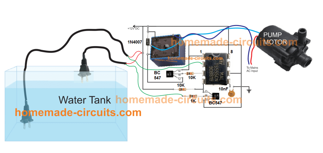
View Simple Water Pump Circuit Diagram Gif. The circuit measures water levels in the tank with the three probes the circuit is using only two transistors and few other components, the three probes used in the circuit should be placed as marked in the schematic. Here is automatic water pump/ tank controller circuit diagram.
5 Simple Water Level Controller Circuits from www.homemade-circuits.com Water level inidicator using tranistor is very simple and easy to make project. As a result, the system immediately deactivates the water pump to protect the electric motor of the water from the circuit diagram (hardware), one can find that very few external components are needed. Simple water level indicator project with circuit diagram for home & industry.
The +9v is supplied to water using a when the water touches the metal contact in which base of each transistor is connected, a small current flows and turns on the transistor.
If water fills above the upper contacts, the pump must switch off. We can use the three different colored leds to create three by doing some modification and attach the motor with the circuit, we can turn on/off the water pump automatically. 736 x 669 png 12 кб. 328 x 172 png 87 кб.

0 Response to "Simple Water Pump Circuit Diagram"
Post a Comment