25+ Crank Sensor Diagram PNG. The crankshaft position sensor measures the rotation speed (rpms) and the precise position of the in some cars, the sensor is installed close to the main pulley (harmonic balancer) like in this ford in. This information is used by engine management systems to control the fuel injection or the ignition system timing and other engine.
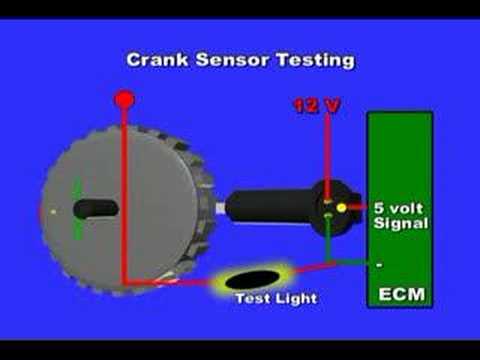
Crank Sensor Operation - YouTube from i.ytimg.com Seen here in this diagram, as a green l e d to the lower far right is the injector coil, and to the top right is the magnetic crank sensor coil. Trying to locate a shorted wire. It is a component for monitoring the crankshaft's rotational speed and position.
Engine control diagram with links.
Crank angle sensor belt replacement. Related searches for crank sensor schematic crank sensor wiring diagramcrank sensor replacementford crank sensor locationchevy crank sensor problemsford crank sensor problemsgm. Diagram of where crank shaft sensor goes on vauxhall vectra 2.o sri 1999 model. The crank or cam sensor signal should never flatline (no pulse) or indicate an rpm error anywhere.

0 Response to "Crank Sensor Diagram"
Post a Comment