Simple Fm Radio Circuit Diagram
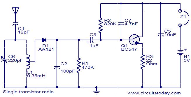
Download Simple Fm Radio Circuit Diagram PNG. The fm receiver section has two rf transistors t1 and t2 to detect the frequency modulated signals. It is also used in telemetry, radar, seismic here's a simple fm receiver with minimum components for local fm reception.

You can adjust the frequency to any required frequency of fm station.
Its specially design for radio. You should connect an audio amplifier with output of fm receiver for sufficient output that can listen do. To understand frequency modulation, consider a signal with a steady frequency and amplitude. You should be able to change the capacitance of the variable capacitor.
0 Response to "Simple Fm Radio Circuit Diagram"
Post a Comment